Dampness Measurement in Concrete Floors
Complex structures like buildings incorporate a number of porous materials like brick, plaster, mortar, timber and concrete. All these materials hold some water within them. This water is mobile and can be transported into the atmosphere and into adjoining materials.
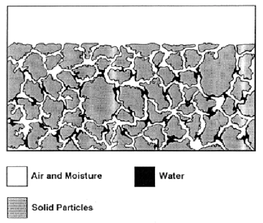
The figure shows the dispersion of water within the pores of a building material like concrete. Water may be present in a material in several different forms:
1. Firstly, there is free water which in many cases can be removed from the material by physical separation.
2. Secondly, bound water which can be present in a material. This is water that is required for chemical combination with the material, in the case of concrete for hydration and chemical absorption. Bound water forms a tighter bond between the water molecules and the solid material. This water is normally not measured and not accounted for in normal drying. Then there is also some water vapour held in the air within the pores of the material.
The migration of water from various pores of a material is by;
(a) capillary action and
s (b) by water vapour diffusion.
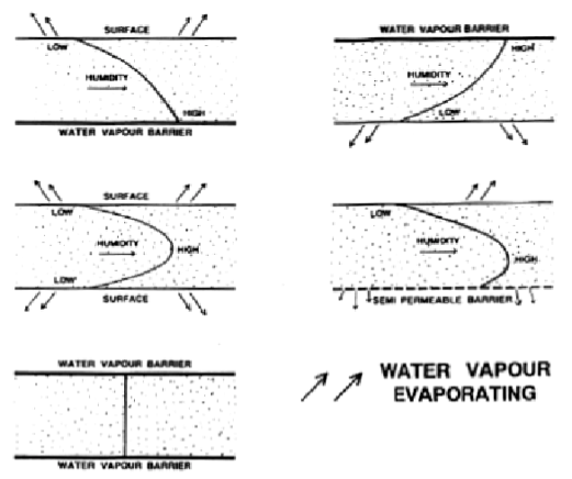
It follows that a "wetter" material will have a higher water or water vapour content. The water vapour pressure will be higher and this will drive the water vapour towards areas where the water vapour pressure is lower (or less water is present). In other words, water vapour will diffuse from a damp area into a dry area. This will continue until such time as equilibrium is achieved or until no further migration can take place.
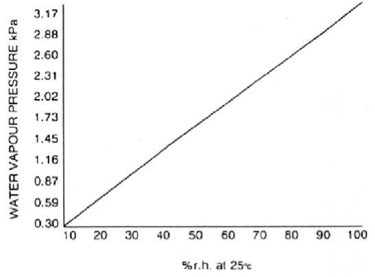
This figure shows relationship between relative humidity and water vapour pressure. Water molecules will migrate from areas of high water vapour pressure (or high relative humidity) towards areas of lower water vapour pressure (lower humidities). Knowledge of the dampness at all points of interest within a building is extremely valuable to a surveyor.
Why Moisture in Concrete is Important
It is necessary to measure and reduce the amount of excess water in concrete after curing for a number of reasons:
1. To determine the time to dry the concrete sufficiently in order to apply a surface covering.
2. To reduce corrosion of reinforcing steel bars.
3. To reduce swelling and biological decay of wood based floor coverings.
4. To prevent alkali attack on polymer based floor adhesives.
5. To predict the final mechanical and physical properties of the concrete.
6. To reduce the extent of alkali silica reaction and carbonation.
7. To study the drying out of various grades of concrete.
Current Methods of Measurement
To date a number of methods are used to measure the "moisture content", namely:
The gravimetric or weight loss method. This relies on a sample being taken from the concrete structure, normally dried in an oven, and the weight loss recorded as a percentage of the final dried sample weight. Apart from not being a site measurement it is difficult to collect a sample without weight loss. Also precautions must be taken to collect a representative sample; for example, a small sample of concrete with a high proportion of large aggregate particles will lead to errors in measurement.
Drying is the most commonly used analytical method for calibration purposes. As discussed earlier, moisture may be present in a material in several different forms, and the loss of water due to heating/drying will depend on the temperature used. A high temperature may remove more bonded water causing discrepancies in measurement. In general this method is justified only when water is the sole constituent which is volatile and there is no degradation of the solid part of the material at elevated temperatures.
The microwave method. At present this is purely a research tool and although microwaves can be used to determine water content, a number of problems exist due to the inhomogeneous nature of concrete and the possibility of the reading being erroneous due to reinforcing steel bars often used in concrete structures .This method is also expensive and not very portable.
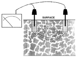
The electrical conductivity method. This relies on the electrical conductivity of the sample increasing with larger amounts of water present. A method exists where two holes are drilled in the concrete and the electrical conductivity is measured using a liquid electrode poured into these holes, as shown in the figure in the previous column. This method also relies on the electrical conductivity calibration being available for the particular mix/type of concrete used. The main advantage of this type of measurement is that it is instant and the instrument does not require frequent recalibration and is relatively rugged. The disadvantage is that there is a limit to the depth of measurement. In practice this is possible for sand/cement mixtures but is a lot more difficult with aggregates or where additives are used and the ratio of sand/cement/aggregate is not known.
The relative humidity method. The amount of free water available at any time will dictate the humidity level of the air in close contact with the concrete, and hence measurement of the relative humidity of the air in close proximity with the concrete can be used as a measure of its free water content. This method is preferable because:
1. The humidity value obtained is universal and does not have to be related to the different materials or the size shape or type of samples.
2. It is not influenced by the composition of the concrete or any additives/chemicals present nor the presence of steel reinforcing bars in the concrete.
3. It is a non contact measurement.
4. Temperature variations and their effects are negligible as the measurement is made within the concrete at the concrete temperature.
The measurement accuracy depends very much on the humidity measuring capability of the instrument/s used. This paper describes the technique and equipment for measuring the high humidities that normally exist in cementitious materials like concrete.
Measurement
Concrete in general is porous and hygroscopic. The solids within the concrete have a pore system, these pores can be filled with water in the liquid or vapour phase. Also, a capillary system is formed between and within the various solids which can also be filled with water.
The different phases in a typical concrete structure are shown in this figure. The drying out process normally transports the liquid water by capillary action to the drying surface and the capillary water is lost from the surface. This action is relatively rapid.
When all capillary water is evaporated diffusion of water below the surface takes place by water molecules changing from the liquid to the vapour phase and diffusing through the pores and capillaries within the concrete. Vapour diffusion is a slower process and this is why the drying out rate is very much slower at the end of the drying period. If part of the drying surface is sealed with an impervious membrane for a while and then the humidity of the air between this membrane and the surface of the concrete is measured, then the value of relative humidity of this air reflects the amount of free water at the surface, but does not necessarily reflect the availability of water well below the surface which could eventually be transported to the surface. This indeed forms the basis of the British Standard method of measurement (BS 8203).
Measurements can also be made by removing a small representative sample which can subsequently be placed in an airtight container into which a measuring probe is also placed. After humidity equilibrium is achieved the humidity value can be read. The advantage of this method is that the measurement can be done off site minimising on site time.
An alternative method is to drill a hole in the concrete and place a humidity measuring probe within this hole, sealed from the outside atmosphere to measure the humidity at depth. The advantages here are:
1. The air inside the hole will then be in good humidity equilibrium with the water/water vapour in the concrete. Although sufficient time should be allowed when the hole is initially drilled for the concrete to settle after the physical and thermal shock of drilling, the time taken to make subsequent measurements is relatively short.
2. The measurement can be made within the thickness of the concrete where the sampling point is more representative of the bulk than at the surface and if the core of the structure has been dried down to a reasonable level of humidity, the possibility of diffusion to the surface is greatly reduced.
For the measurement of humidity a number of devices which could be inserted into a hole drilled into the concrete have been available for some time. However, all these devices suffer from a number of faults like instability, inaccuracy, sensor failure and sensor drift due to contamination requiring frequent recalibration and servicing/ replacement. These problems are particularly serious at the high humidities that exist in the boundary layer adjacent to most concrete surfaces. Hence the measurement has to be done with the highest possible repeatability and accuracy with systems which have inherently low drift and do not require frequent calibration.
Apparatus for Humidity Measurement
What is required is a reliable instrument capable of measuring humidity with the highest possible accuracy. It is well known that an excellent method of measurement of moisture content or humidity in the atmosphere is the measurement of dewpoint by the use of dew formation on a chilled mirror, where the measurement accuracy is a function of the mirror's temperature sensor performance rather than the measurement or electrical parameters of the absorptive properties of chemical films.
For the measurement of humidity, two parameters must be known, the ambient temperature and the dewpoint temperature of the atmosphere. The ambient temperature measurement is reasonably straightforward and a number of devices are available which give good accuracy and repeatability.
However, good dewpoint measurement has until now been available only using instruments which require the air sample to flow through a measuring head. This makes measurement impossible in a static environment such as the void within a concrete structure.
The instrument and measuring technique described here combine the precision and repeatability of chilled mirror dewpoint measurement with the operational simplicity and size of hand held hygrometer probes. The probe had its own expanding ring which could trap the air in the void where the measuring tip was placed.
All the materials used within the measuring tip are specially selected for their low thermal conductivity and low moisture absorption properties, for example stainless steel, delrin and solid gold for the mirror.
None of these components are prone to deterioration or require replacement from normal use. The length of probe available is such that the tip can be placed at the centre of a fairly large thickness of concrete. Such a probe coupled with an instrument which could measure on site, without mains if necessary, and could log results for inspection later.
The Findings
The equipment described above can be used in a number of ways. The easiest is to leave a probe in situ throughout the critical drying period of the concrete. Measurements can also be made at different depths within the concrete. This information can be used to study the humidity/moisture profile within the thickness of the concrete.
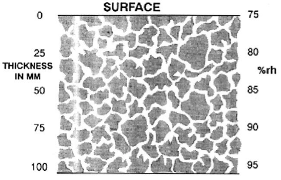
The above figure shows an averaged profile of humidity/moisture distribution for several types of concrete structures after some drying.
This figure shows several different humidity/moisture profiles for different types of structures. It is obvious that the humidity/moisture profile shows higher humidities at depth.
These higher humidities will redistribute and diffuse through the structure eventually causing high humidity/moisture at the surface after a covering material has sealed the surface preventing further drying. For this reason it is important to have some knowledge of the highest humidity present in the concrete before covering.
-
 PROTIMETER
Protimeter GRN3100 GrainMaster i2 Grain Moisture Meter
Item Number:
GRN3100
Packaging Unit: 1 / each
PROTIMETER
Protimeter GRN3100 GrainMaster i2 Grain Moisture Meter
Item Number:
GRN3100
Packaging Unit: 1 / each
-
 PROTIMETER
Protimeter GRN6165 BaleMaster with 600mm probe
Item Number:
GRN6165
Packaging Unit: 1 / each
PROTIMETER
Protimeter GRN6165 BaleMaster with 600mm probe
Item Number:
GRN6165
Packaging Unit: 1 / each
-
 NOBRAND
Rubert Composite Surface Roughness STD
Item Number:
RUB30695STD
Packaging Unit: 1 / each
NOBRAND
Rubert Composite Surface Roughness STD
Item Number:
RUB30695STD
Packaging Unit: 1 / each
-
 PROTIMETER
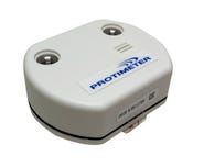
Protimeter BLE Bluetooth Low Energy Environmental Logger
Item Number:
BLELOGGER
Packaging Unit: 1 / each
PROTIMETER
Protimeter BLE Bluetooth Low Energy Environmental Logger
Item Number:
BLELOGGER
Packaging Unit: 1 / each
-
 PCWI
Neon Holder for DC15 and DC30 PCWI Detector Handles
Item Number:
NEONHOLDER
Packaging Unit: 1 / each
PCWI
Neon Holder for DC15 and DC30 PCWI Detector Handles
Item Number:
NEONHOLDER
Packaging Unit: 1 / each
-
 PCWI
Fuse for DC15 and DC30 PCWI DC Detectors
Item Number:
FUSEDC
Packaging Unit: 1 / each
PCWI
Fuse for DC15 and DC30 PCWI DC Detectors
Item Number:
FUSEDC
Packaging Unit: 1 / each
-
 PCWI
Fuse for P40 and P20 PCWI Pulse Detectors
Item Number:
FUSEPULSE
Packaging Unit: 1 / each
PCWI
Fuse for P40 and P20 PCWI Pulse Detectors
Item Number:
FUSEPULSE
Packaging Unit: 1 / each
-
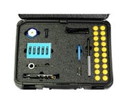 PROTIMETER
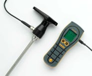
Protimeter BLD4755-KIT Flooring Kit Excluding MMS3 Instrument - CLEARANCE PRICE: $1270.00
Item Number:
BLD4755-KIT
Packaging Unit: 1 / each
PROTIMETER
Protimeter BLD4755-KIT Flooring Kit Excluding MMS3 Instrument - CLEARANCE PRICE: $1270.00
Item Number:
BLD4755-KIT
Packaging Unit: 1 / each
-
 DEFELSKO
Defelsko HHD Half Circle Neoprene Brush 50-127mm/2-5"
Item Number:
HHDHCBRSH5
Packaging Unit: 1 / each
DEFELSKO
Defelsko HHD Half Circle Neoprene Brush 50-127mm/2-5"
Item Number:
HHDHCBRSH5
Packaging Unit: 1 / each
-
 DEFELSKO
Defelsko BHI Test Disk-Extra Soft (5 pk) w/ Plate
Item Number:
BHITESTXS
Packaging Unit: 1 / each
DEFELSKO
Defelsko BHI Test Disk-Extra Soft (5 pk) w/ Plate
Item Number:
BHITESTXS
Packaging Unit: 1 / each
-
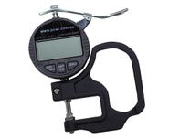
 DEFELSKO
Precision Plastic Shim Set of 4 for Testex Micrometer
Item Number:
STDRTSHIMS
Packaging Unit: 1 / each
DEFELSKO
Precision Plastic Shim Set of 4 for Testex Micrometer
Item Number:
STDRTSHIMS
Packaging Unit: 1 / each
-
 PCWI
Anodised Aluminium Combs 4 Sided Pack of 100
Item Number:
WETCOMB100
Packaging Unit: 1 / each
PCWI
Anodised Aluminium Combs 4 Sided Pack of 100
Item Number:
WETCOMB100
Packaging Unit: 1 / each
-
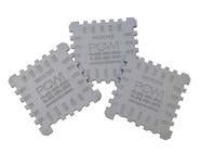
 PCWI
Coating Thickness Standards Non-Ferrous 5 Plates PA
Item Number:
NFPASTD5PL
Packaging Unit: 1 / each
PCWI
Coating Thickness Standards Non-Ferrous 5 Plates PA
Item Number:
NFPASTD5PL
Packaging Unit: 1 / each
-
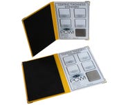
 PCWI
Digital Gauge For Testex Tape Certified
Item Number:
TESTXGAUGE-C
Packaging Unit: 1 / each
PCWI
Digital Gauge For Testex Tape Certified
Item Number:
TESTXGAUGE-C
Packaging Unit: 1 / each
-
 PCWI
Coating Thickness Standards Non-Ferrous 5 Plates PC
Item Number:
NFPCSTD5PL
Packaging Unit: 1 / each
PCWI
Coating Thickness Standards Non-Ferrous 5 Plates PC
Item Number:
NFPCSTD5PL
Packaging Unit: 1 / each
-
 PCWI
Coating Thickness Standards Non-Ferrous 5 Plates LD
Item Number:
NFLDSTD5PL
Packaging Unit: 1 / each
PCWI
Coating Thickness Standards Non-Ferrous 5 Plates LD
Item Number:
NFLDSTD5PL
Packaging Unit: 1 / each
-
 PCWI
Coating Thickness Standards Non-Ferrous 5 Plates GD
Item Number:
NFGDSTD5PL
Packaging Unit: 1 / each
PCWI
Coating Thickness Standards Non-Ferrous 5 Plates GD
Item Number:
NFGDSTD5PL
Packaging Unit: 1 / each
-
 PCWI
Coating Thickness Standards Ferrous 5 Plates PC
Item Number:
FPCSTD5PL
Packaging Unit: 1 / each
PCWI
Coating Thickness Standards Ferrous 5 Plates PC
Item Number:
FPCSTD5PL
Packaging Unit: 1 / each
-
 PCWI
Coating Thickness Standards Ferrous 5 Plates PA
Item Number:
FPASTD5PL
Packaging Unit: 1 / each
PCWI
Coating Thickness Standards Ferrous 5 Plates PA
Item Number:
FPASTD5PL
Packaging Unit: 1 / each
-
 PCWI
Coating Thickness Standards Ferrous 5 Plates LD
Item Number:
FLDSTD5PL
Packaging Unit: 1 / each
PCWI
Coating Thickness Standards Ferrous 5 Plates LD
Item Number:
FLDSTD5PL
Packaging Unit: 1 / each